last modified: Tuesday, 30-Dec-2025 22:49:39 CET
Document status: usable, section on twinning missing
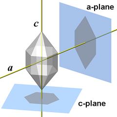
This chapter introduces the crystal structure of quartz and its relation to the symmetry and the physical properties of quartz crystals.
All renderings are based on a single data set of quartz unit cell coordinates downloaded from the now orphaned site www.molecules.org.
|
Introduction - Looking through a Microscope
|
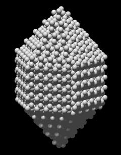
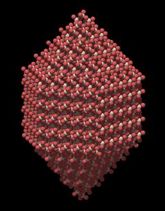
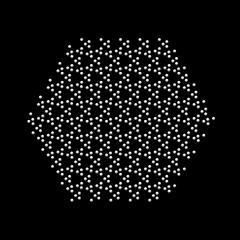
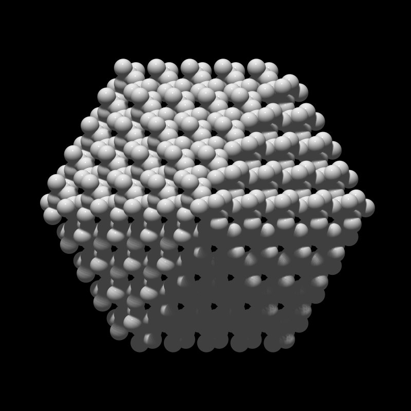
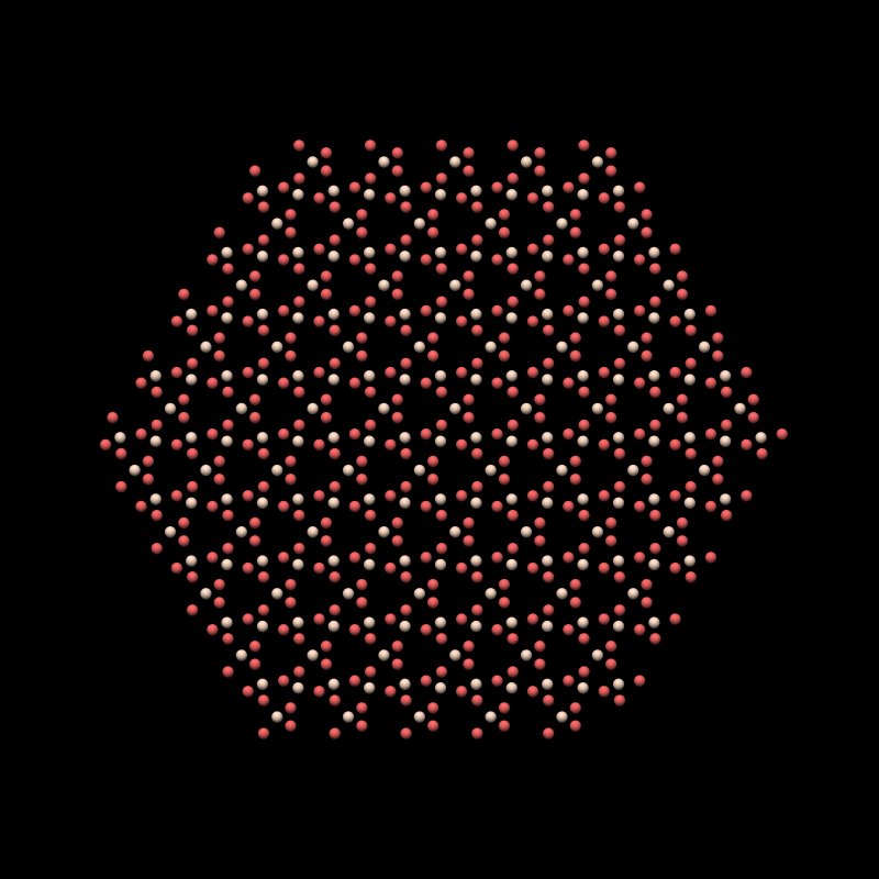
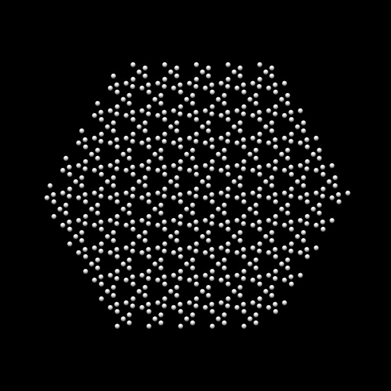
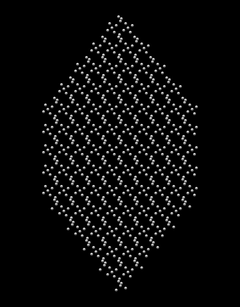
Of course, this rendering is based on the assumption that atoms are just small, hard balls of identical size. Also note that while the relative positions of the atoms are correct, this is probably not an accurate model of quartz surface structure (I do not have any empirical data on that). But to explain the internal structure and the symmetry properties, it is good enough.
As one would expect from a crystal, one can see that there are some repeating patterns, so there is a regular structure, but as a whole it looks quite complex. The first impression is that of a very densely packed structure.
|
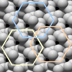
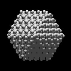
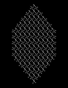
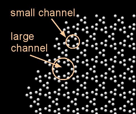
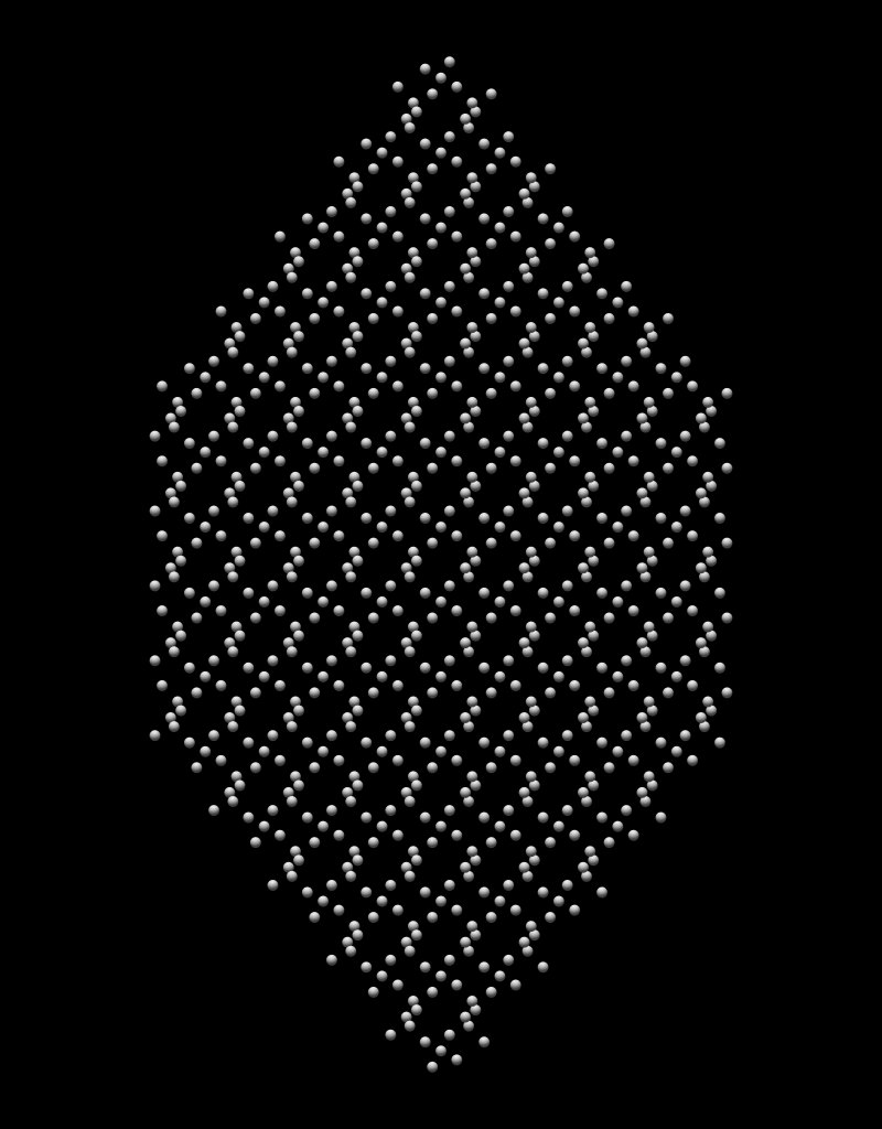
There are apparently hexagonal patterns that correspond to the six-sided prism of the crystal, a few examples are shown in Fig.2.03.
Another interesting feature are black holes, gaps in the structure. Since this is a top view of a three-dimensional crystal, these gaps are actually channels that run through the entire crystal, parallel to the c-axis. So the internal structure of quartz is not as tight as it first seemed.
The SiO4 Tetrahedron
|
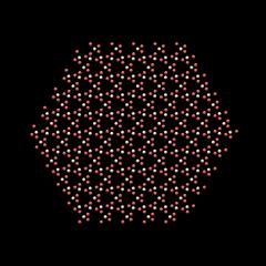
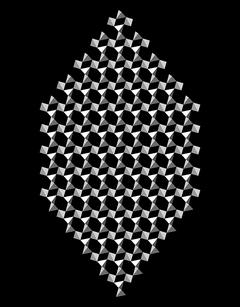
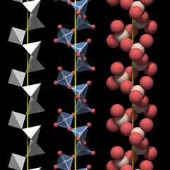
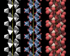
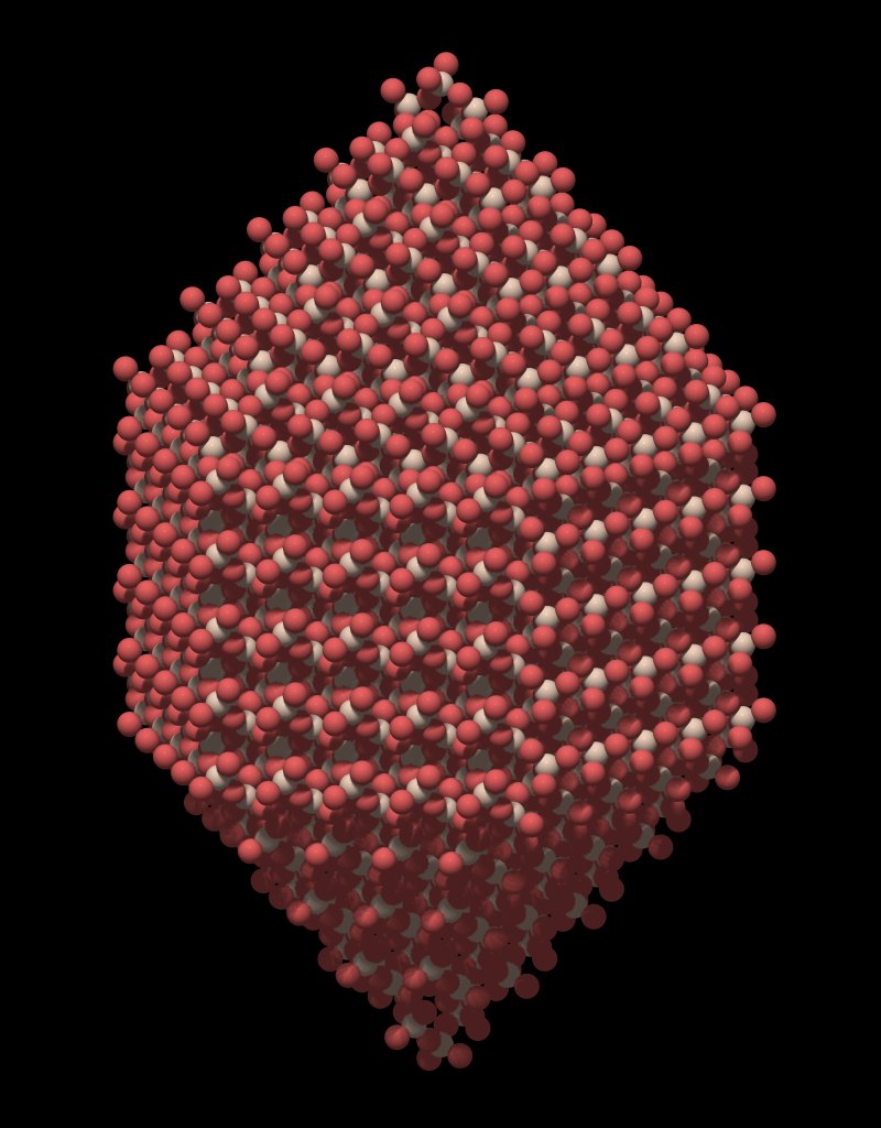
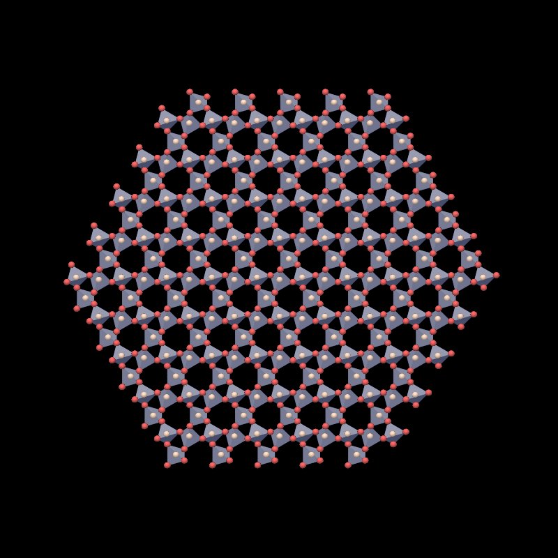
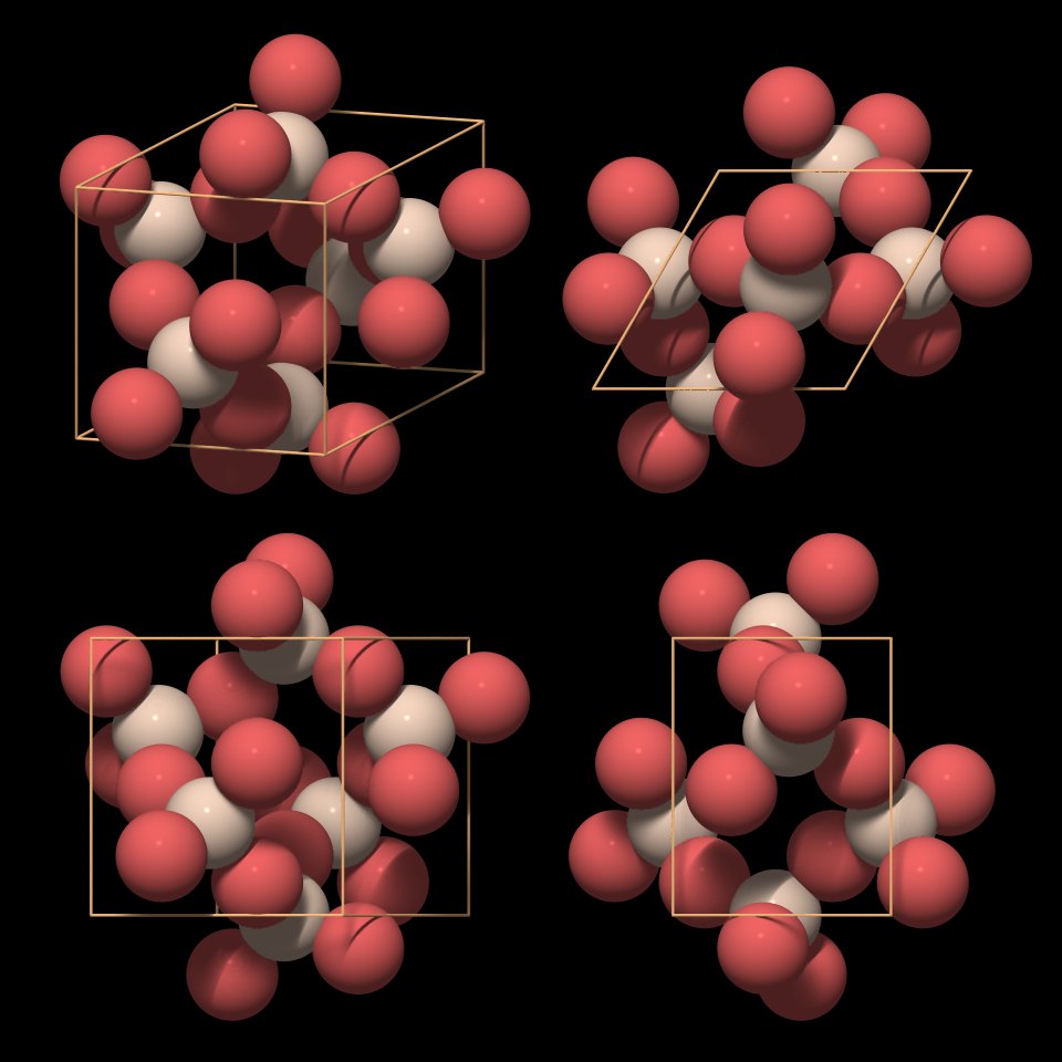
Figure 3.01 shows a rendering of a quartz crystal similar to the one in Fig.2, with the atoms rendered as equally sized balls, but with a slightly smaller diameter. Silicon atoms are colored white and oxygen atoms are colored red.
In a real crystal, the oxygen atoms on the surface each have an additional small hydrogen atom attached. Inside an ideally grown crystal hydrogen will be completely absent, and since we are interested in the crystal structure, the hydrogen atoms have not been rendered.
This figure is nice but not very helpful for understanding the underlying structure and we need to change the perspective to gain more insight.

|
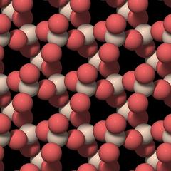
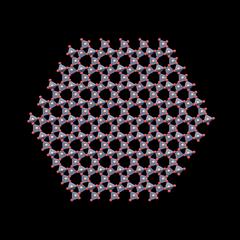
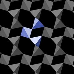
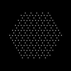
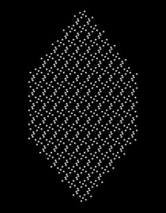
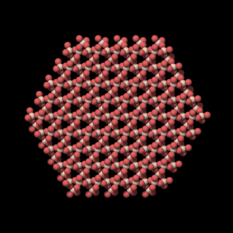
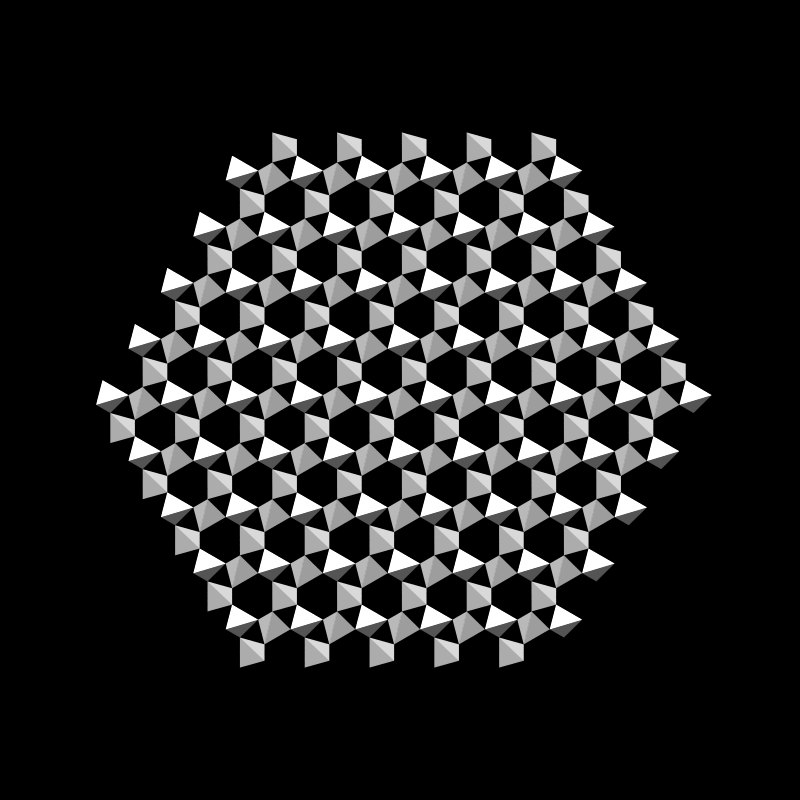
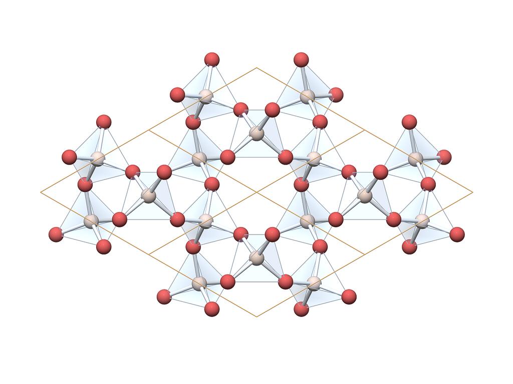
Figure 3.02 shows a cut through the crystal along a c-plane. This is not simply a slice of the crystal with a layer of atoms, it is a top view of the crystal structure, and the atoms in it lie in different planes. So the gaps in the structure are channels that run through the entire crystal parallel to the c-axis; they have already been shown in Fig.2.02.
Each silicon atom is surrounded by and connected to 4 oxygen atoms, and each oxygen atom is connected to 2 silicon atoms. As explained in the chapter Chemical Properties the silicon oxygen bond is polar and covalent and not ionic. Individual silicon and oxygen atoms cannot move freely within the crystal. Thus quartz is said to have a macromolecular structure.
An ideal quartz crystal is one large molecule.
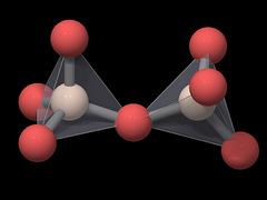
|
|
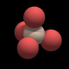
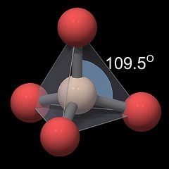
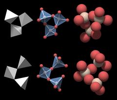
Each oxygen atom has the same distance to the silicon atom, and the distances between the oxygen atoms are also all the same.
|
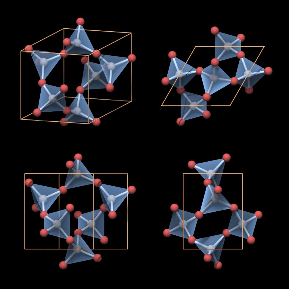
Each of the 4 oxygen atoms is linked to another silicon atom in a neighboring tetrahedron, so the SiO4 tetrahedra share their oxygen atoms and the overall formula of quartz is SiO2.
Quartz can thus be described as a network of interconnected SiO4 tetrahedra, and it is classified as a network silicate or tectosilicate.
|
Basic Elements of the Structure
A crystal is a solid body with a homogeneous regular internal structure. It is built up by a periodic repetition of basic elements. Those basic elements can be atoms, ions, entire molecules, or groups of them. A geometrical element that is periodically repeated to form a regular pattern is called a motif, and, in a sense, we look for motifs in the crystal structure.The basic structural element in quartz is not a SiO2 molecule, such a molecule does not exist. And although the SiO4 tetrahedron can be considered the basic building block of quartz, it is not sufficient for characterizing quartz: there are other silica modifications with the same chemical formula that belong to different crystal systems.
So the task is to identify the characteristic element that defines the crystal structure of quartz. Or put another way: we try to find the motif that determines the pattern given in the crystal structure of quartz.
A valid motif must also reflect the chemical composition of quartz, one part silicon and two parts oxygen, so it could have a "formula" of Si2O4 or Si9O18, for example.
|
|
|
|
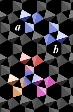
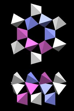
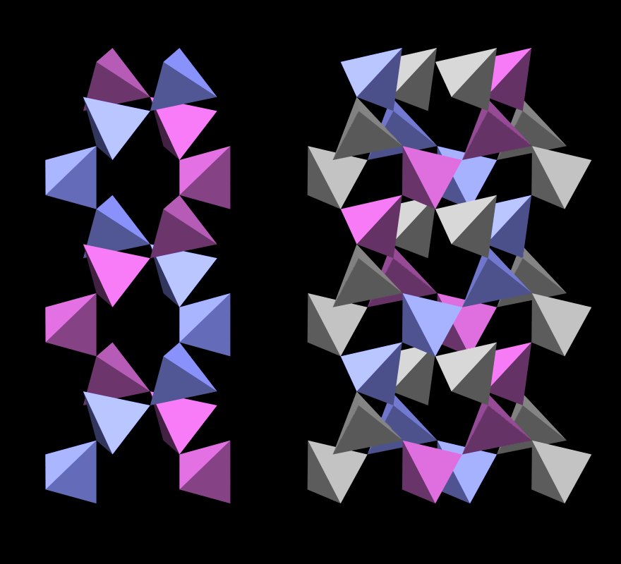
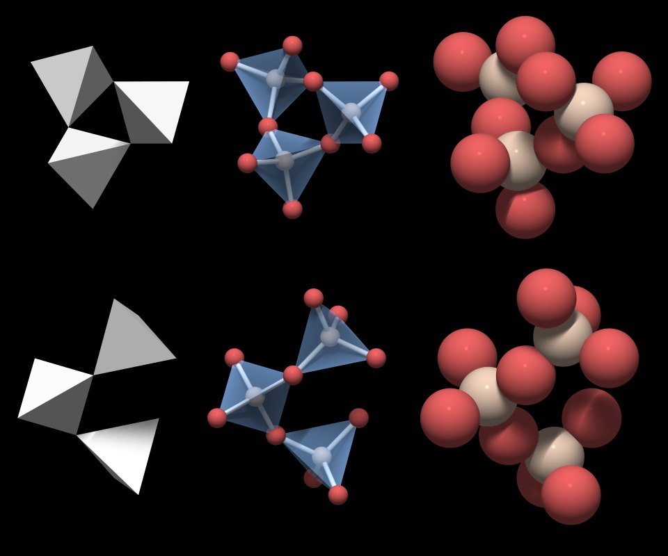
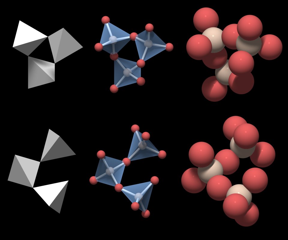
The basic structural unit of quartz is a group of three connected SiO4 tetrahedra.
Although each of the motifs a and b alone suffice to build up the entire crystal structure, it is worth mentioning that neighboring motifs share one SiO4 tetrahedron to form a group of 5 tetrahedra.
As exemplified in the lower part of Fig.4.04 for motif b (multicolored with a blue center), each motif is surrounded by three motifs of the other type (orange, red, purple). That way each of the SiO4 tetrahedra is part of motif a and motif b.
(Right now it might not clear what the point about it is, but it is an important finding and we will come back to this later).
The shadows in the rendering indicate that the three SiO4 tetrahedra do not form a closed triangle - this would be an impossible geometrical figure.
|
|
This is motif a from Fig.4.04, but it would work just as well for motif b.
|
Now, there seems to be a little problem. A valid motif of the crystal structure should reflect the chemical formula of quartz, and the group in Fig.4.07 does not: if you count the atoms, its formula is Si3O10. Of course that is so because it is displayed as an isolated molecule. Inside the network of tetrahedra each oxygen is shared by two SiO4 tetrahedra, so the formula computes as (SiO4/2)3, which will give Si3O6.
The chemical formula of the basic structural unit of quartz is Si3O6.
Note: there is an alternative way of choosing a motif of the crystal structure that also works in an atomic lattice: that motif is the unit cell. Because it is defined in a more abstract way and looks confusing to the uninitiated, it is introduced later.
Helices
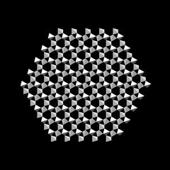
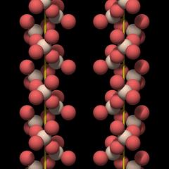
|
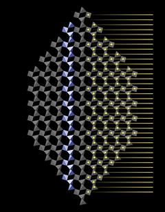
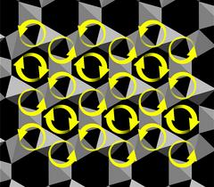
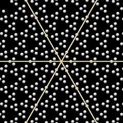
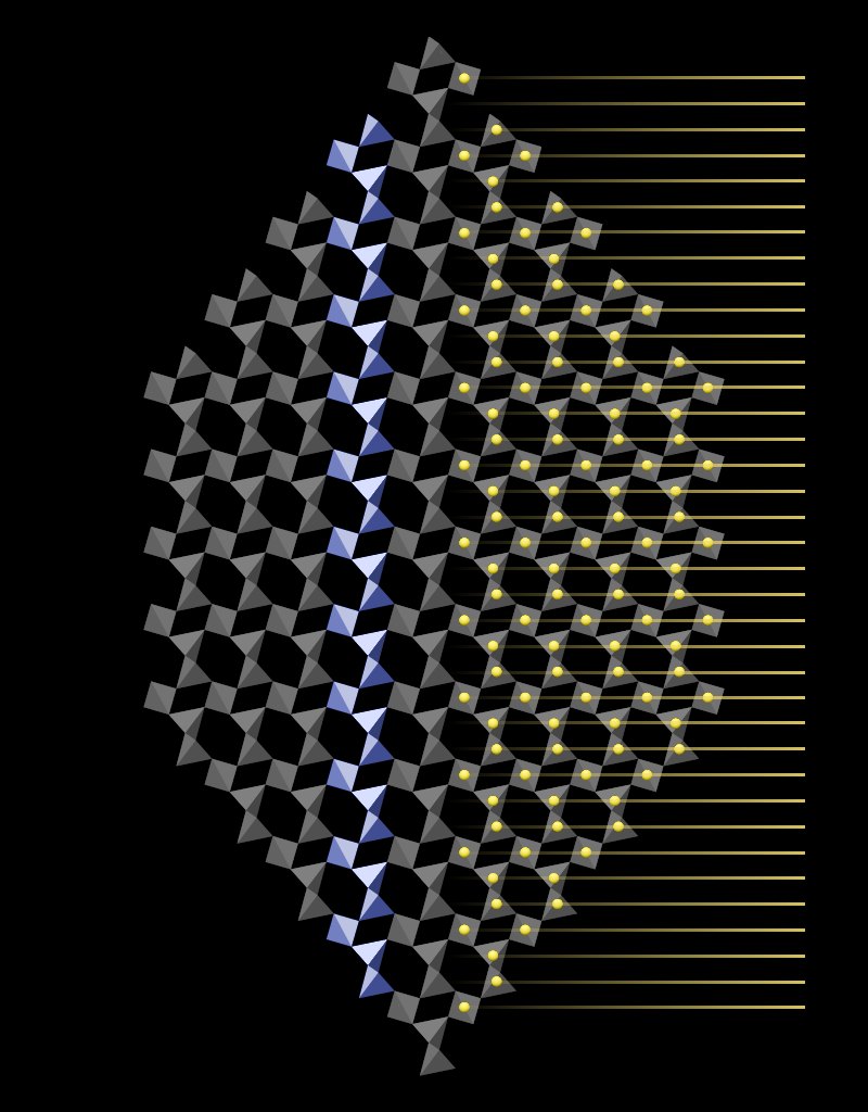
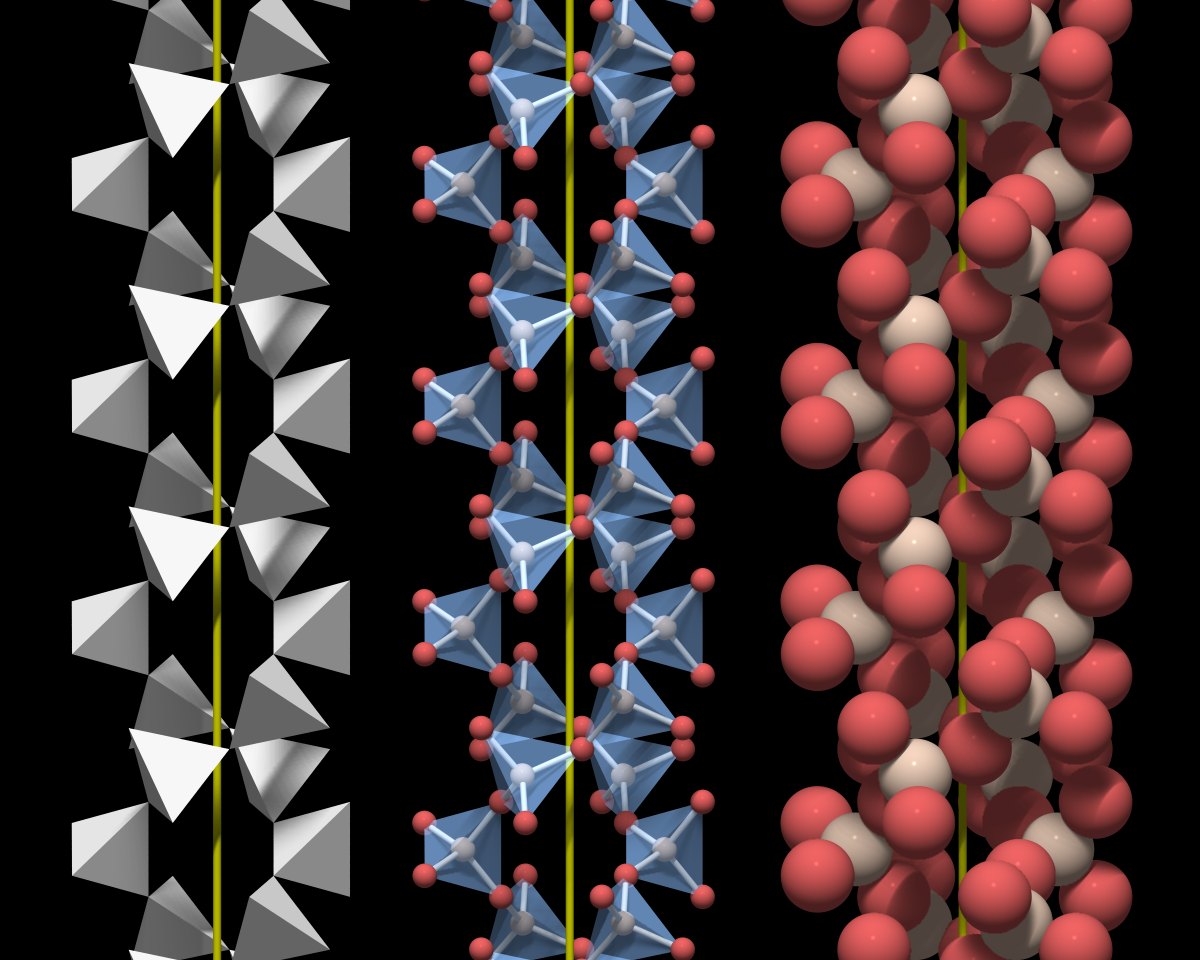
The silicon atoms at the center of the tetrahedra occupy places on horizontal planes. In the right half of the crystal in Fig.5.01 silicon atoms (yellow dots) have been projected onto the tetrahedra pattern. The yellow horizontal lines that extend to the right demonstrate that these planes are evenly spaced along the vertical axis (or c-axis).
|
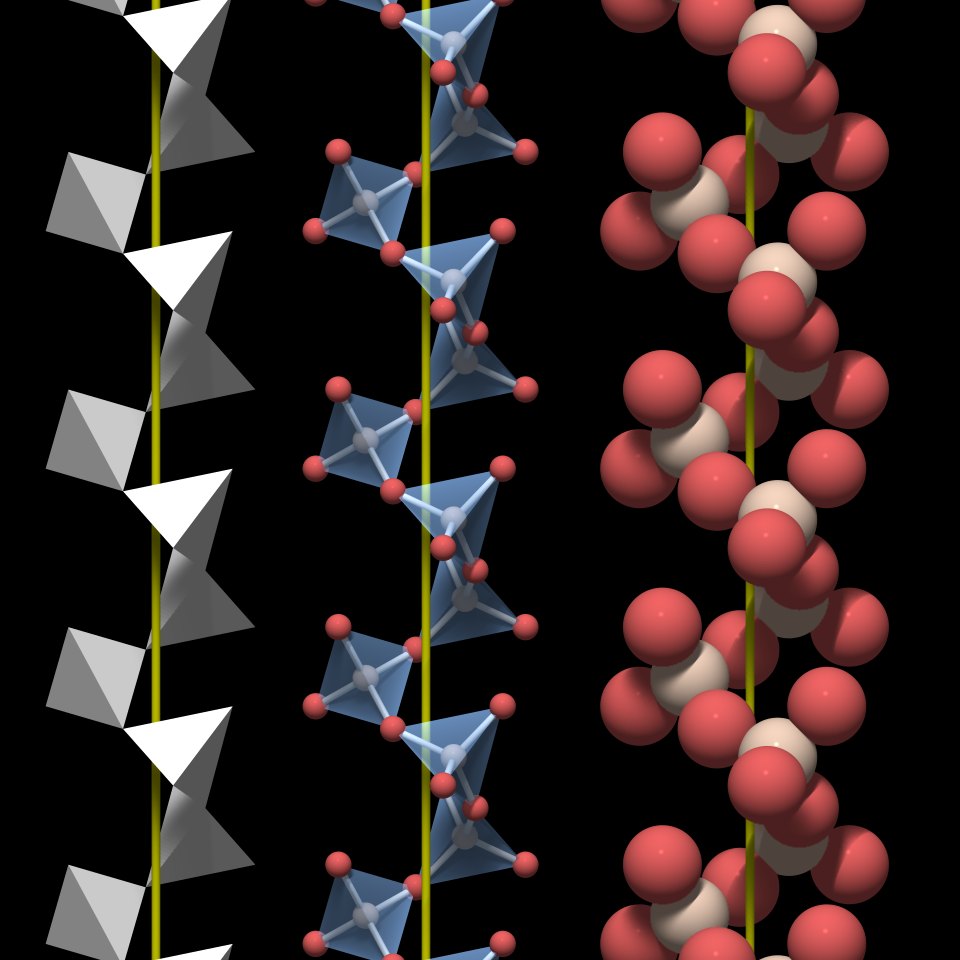
Of course, these helices are virtual bodies - there is nothing that distinguishes the chemical bonds that connect the SiO4 tetrahedra within a particular helix from bonds to tetrahedra outside that helix. Quartz does not have a fibrous structure and it does not break more easily parallel to the c-axis. But the helices are a geometrical feature of quartz that has important implications for its symmetry.
In quartz SiO4 tetrahedra are arranged in virtual threefold helices that run parallel to the c-axis.
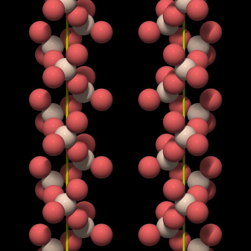
|
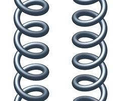
First of all, a helix winds around a central axis either clockwise or counterclockwise. Clockwise and counterclockwise corresponds to being right-handed and left-handed. The left helix in Fig.5.03 is left-handed, the right one is right-handed. To determine the handedness of a helical structure (a screw for example) you place it upright in front of you and follow the helix downward with your finger. If the finger moves clockwise, the helix is right-handed. The helices shown in Fig.5.02 are left-handed.
|
This also means that you cannot bring a right-handed and a left-handed helix into congruence. To cite Wikipedia: "Handedness (or chirality) is a property of the helix, not of the perspective: a right-handed helix cannot be turned or flipped to look like a left-handed one unless it is viewed through a mirror, and vice versa."
The consequence:
A helix has no mirror symmetry.
Thus a structure that is entirely made of either a right- or a left-handed helical structure cannot show mirror symmetry. As explained in the last section (see Fig.5.02), chains of SiO4 tetrahedra form helices that run vertically through the entire crystal, and in fact quartz lacks mirror symmetry.
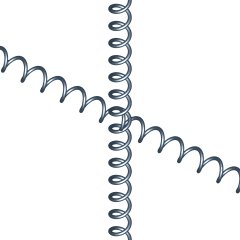
And that a helix is congruent with itself when rotated by 180° is in accordance with the fact that both ends of a quartz crystal show the same types of crystal faces.
I should stress that the helix is just a virtual body that helps to visualize an inherent symmetry property of the crystal structure of quartz, its handedness.
Large Channels and Double Helices
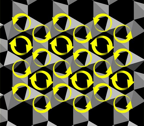
A very distinctive feature of quartz crystal structure is the presence of channels that run through the entire crystal parallel to the c-axis.These channels are an important element of the crystal structure because they are wide enough to take up small cations.

|
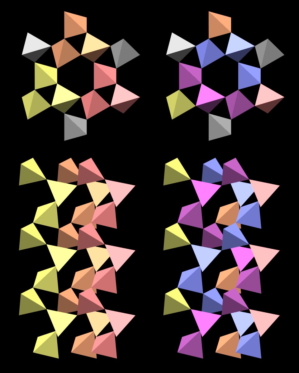
The structure is a complete ring that is roughly hexagonal. If one could take it out of the crystal, it would not fall apart.
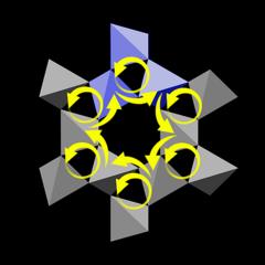
|
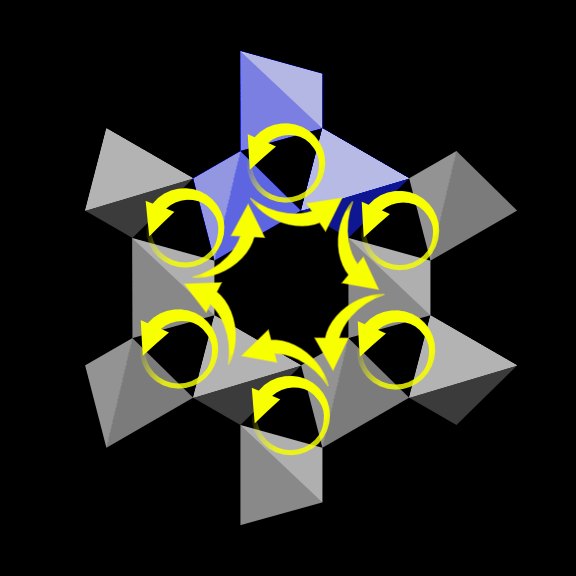
Let us look at the topmost motif in the ring, marked blue, and the two tetrahedra that are part of the wall of the central channel. Because the helix is left-handed, the right tetrahedron is lower than the left one, and this downward step is indicated by a short yellow arrow.
The same is true for all motifs. So if we pick one of the six central tetrahedra and move to the next one in clockwise direction, then to the next one and so on, we will describe a circle with a downward motion. In other words:
The tetrahedra that surround the large channels form a sixfold helix.
Now the ring structure shown in Fig.6.01 is only three tetrahedra high, so a sixfold helix around the central channel cannot be complete. Instead, the tetrahedra form two independent arcs made of three SiO4 tetrahedra at opposite sides of the channel, colored blue and purple in Figure 6.03.
At the bottom of Fig.6.02 we see that both arcs are winding down clockwise.

|
This double helix is made of two sixfold helices that wind around each other with the same handedness (in this case both are right-handed). They are independent, that is, they do not directly touch each other. Both helices are connected by the outer gray tetrahedra.
The walls of the central channels are made of a sixfold double helix of tetrahedra.

|
|
The sixfold double helix and the threefold helices are of opposite handedness.
And another fact that can be found when inspecting Fig.6.06:
Each SiO4 tetrahedron is member of 2 threefold and 2 sixfold helices.
|
natural DNA         Quartz Design
 5'      3'         5'    3'
 PR-A::T-RP         PR-A::PR-A
 PR-G::C-RP         PR-G::PR-G
 PR-C::G-RP         PR-C::PR-C
 PR-C::G-RP         PR-C::PR-C
 PR-A::T-RP         PR-A::PR-A
 PR-T::A-RP         PR-T::PR-T
 3'      5'         3'    5'
In a quartz-type DNA the members of individual base pairs would simply be two identical molecules, and they would not face each other, but point in the same direction. In quartz, equivalent sides of a pair of tetrahedra do not face each other because they both assume the same orientation in space and "point" in the same direction. And of course the tetrahedra do not attract each other as the members of a base pair do.
Rotational and Mirror Symmetry
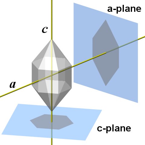
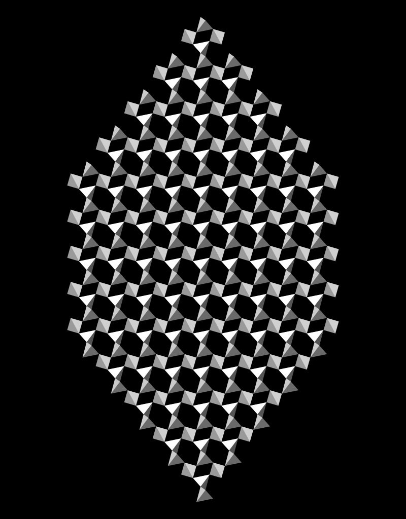
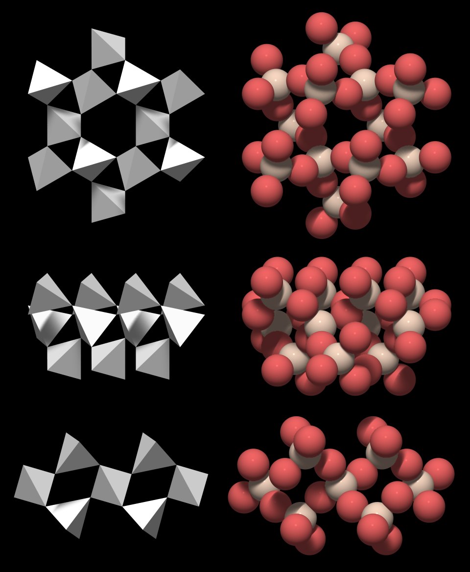
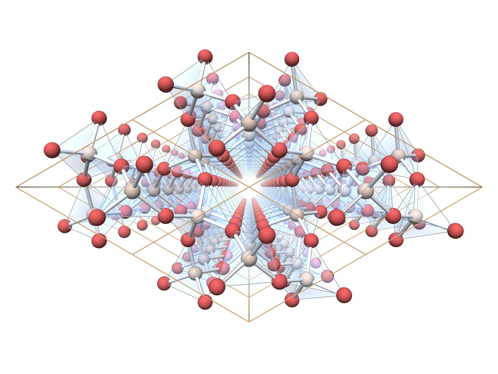
All symmetry properties of quartz can be deduced from the figures and findings that have been presented above. But to explicitly discuss them along with the other properties of the structure would have complicated the already long-winded presentation. So I start all over again and follow an independent approach.To get a better idea of the rotational and mirror symmetry of quartz crystal structure, we project the atoms onto the a- and the c-plane (compare to Fig.1.01). We treat all atoms equal and for now do not distinguish silicon and oxygen atoms.
|
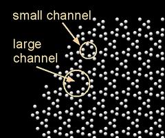
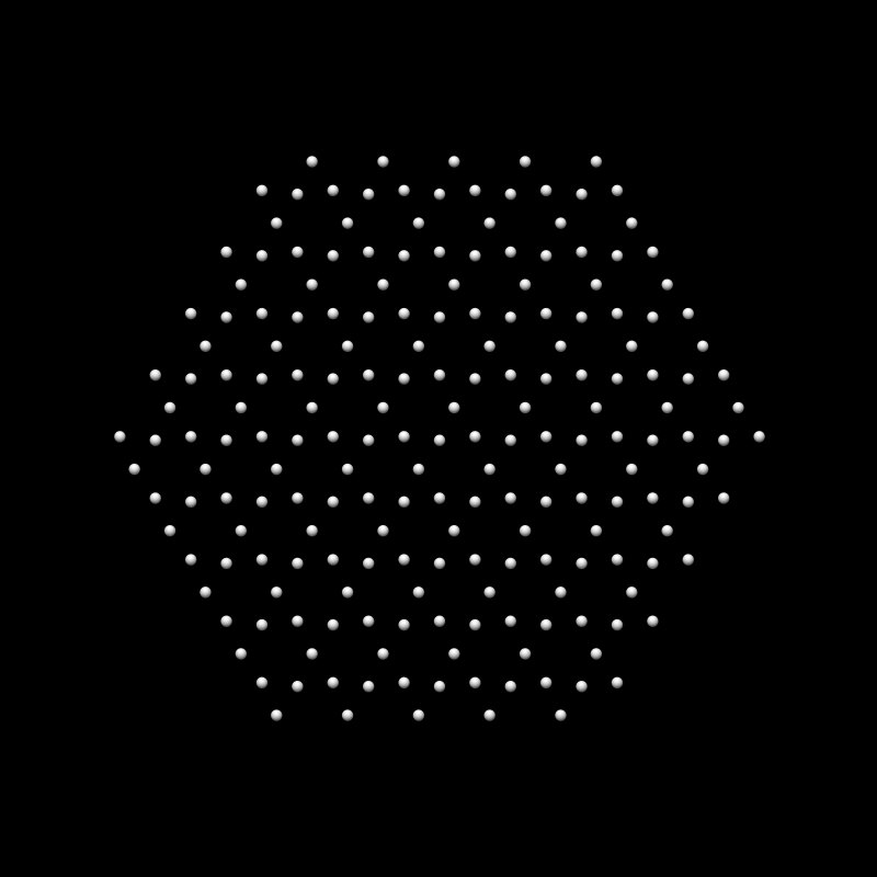
We see large channels that correspond to the small gaps in Fig.2, and twice as many smaller channels (see Fig.7.02).
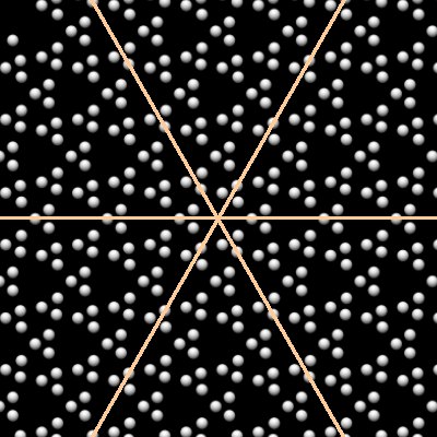
This is obviously not a hexagonal structure, it is trigonal and has a threefold rotational symmetry. If you take that pattern and rotate it by 120°, it will match, but if you just rotate it by 60°, it will not.
At first it seems that this is only so because the pattern is made of triangular groups of three atoms, but that's not all that is to it.
|
|
Quartz does not show mirror symmetry, however, and the mirror symmetry of the pattern is only an apparent one - so far we have disregarded the fact that the structure is three-dimensional.
|
If this pattern is rotated by 180° it will look the same, it shows twofold rotational symmetry. This sounds rather trivial, but remember that this is not true for the trigonal pattern in Fig.101, it has to be rotated by 120° to match, and a 180° rotation will not work.
|
We can summarize that quartz is trigonal and shows
It is accordingly given a Hermann-Mauguin symbol of 32 (read "three-two").
The pattern seen when viewing down the c-axis (Fig.7.01) is very different from the pattern seen when viewing along an a-axis (Figs.7.05 and 706). Such a structure will likely react differently to forces acting from different directions, it is anisotropic. This anisotropy of quartz in fact has important technical implications.
Handedness
|
The basis of this handedness in crystal morphology is the handedness of the internal structure, as found in the handedness of its elementary unit (the group of three SiO4 tetrahedra) and in the handedness of the virtual helices that are made up by these groups.
All figures that have been presented so far show renderings of a right-handed quartz structure. We will have a look at the key elements of quartz crystal structure to see how they change with handedness.

|

The differences are subtle. The handedness can be determined by checking if the hook described by the three tetrahedra runs in a clockwise or counter-clockwise direction.
Although the outer shapes of the models are very similar, it is not possible to bring them into congruence, no matter how you rotate them. For example, the tetrahedra in the upper left top views of both figures point in different directions.
|
The handedness of quartz crystal structure is not only expressed in the geometry of quartz crystals, it also plays a role in its optic properties. Quartz is an optically active substance: it rotates the polarization plane of light that passes through it along its c-axis (see the chapter Physical Properties for an introduction).
The relationship between the handedness of the threefold virtual helices, the morphology and the physical properties is straightforward. The following table lists morphological, structural and optical features of left- and right-handed quartz.
Unit Cell of Quartz
|
So far we have identified a few possible motifs of quartz crystal structure, one of them is presented again in Fig.10.01. These motifs could be used to build up the entire three dimensional pattern simply by periodically repeating them in space. But what has this strangely formed hook made of three SiO4 tetrahedra to do with the six-sided prisms of a quartz crystal?
It is obviously very difficult to grasp the relationship between the geometry of the motif and the geometry of the crystal.
Crystallographers follow a different approach. They describe the crystal structure quantitatively and look for measures that help to relate the structure to the outer shape of the crystal.
They work with the unit cell concept:
-
The unit cell is the smallest spatial fraction of a crystal that shows all its symmetry properties.
-
The point lattice defines a virtual coordinate system with three axes within the crystal structure. It is constructed by tiling unit cells in three dimensions.
- The unit cell is the base element of the point lattice. Its "points" correspond to the corners of the unit cells.
- The unit cell encloses the motif of the crystal lattice.
- A unit cell is necessarily enclosed by parallelograms: Only parallelograms can be tiled to cover a plane without leaving gaps in between them.
The benefit of this approach is that the positions of the atoms in the crystal structure, the geometry of crystallographic forms and the position of the corresponding crystal faces can now all be defined with respect to a single coordinate system.
This is all a bit abstract, but it becomes quite clear once we look at a "real" unit cell. Since we already know a possible motif of quartz crystal structure, it is fairly easy to figure out the shape and the dimensions of its unit cell.

|
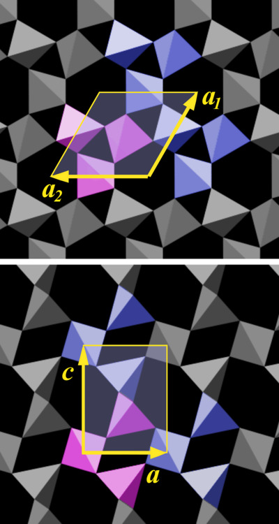
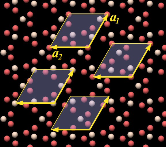
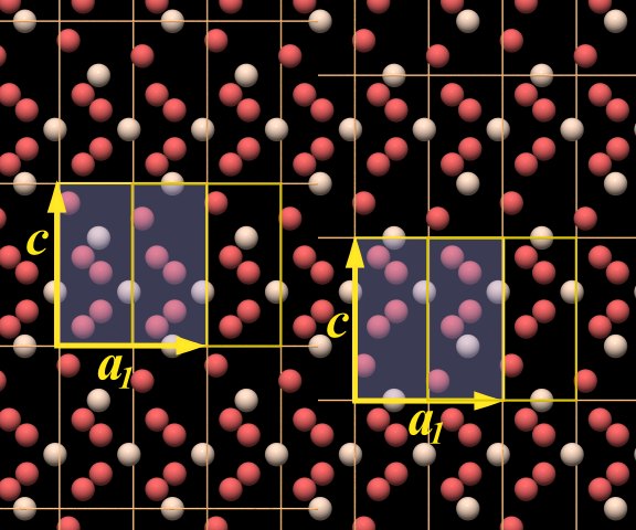
We pick motif a, marked as a purple group of tetrahedra in Fig.10.02, and measure how its copy must be shifted to built up the pattern of the crystal structure. One can just select some arbitrary element within the motif, for example the joint between two tetrahedra (the position of an oxygen atom) and determine the direction and the distance to the nearest equivalent point in the crystal lattice. This works with any motif of the structure, of course.
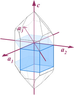
The upper part of Fig.10.02 is a view of the c-plane, a close-up of what is shown in Fig.4.03. There are essentially three different directions along which the motif is tiled, indicated by three yellow arrows, designated a1 and a2. These arrows all have the same length. a3 is omitted, because it is unnecessary for building up the pattern[5]. The arrows a1 and a2 define a parallelogram, the geometric figure we look for. A beginner will likely pick a triangle or a hexagon, as the motif itself has a roughly triangular shape and can be repeated in six directions. But only a parallelogram can be tiled to cover a plane without leaving gaps[6].
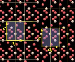
What is still missing is the vertical dimension of the unit cell. In the lower part of Fig.10.02 we look at the m-face of a crystal, parallel to an a-axis. Here the two arrows, designated c and a1 (the one already shown in the upper part of the figure), define another parallelogram, in this case a rectangle. Arrow c is longer than arrow a1 (and in turn a2 and a3), the ratio of their lengths is:
c : a = 1.10013 : 1
The absolute length of the axes is:
a 0.49133 nm or 4.9133 Å
c 0.54053 nm or 5.4053 Å
|
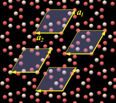
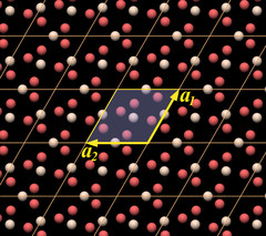
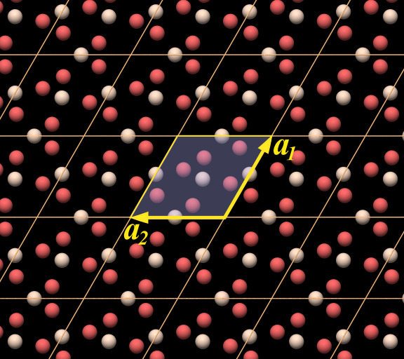
So far we have only determined the dimension of the unit cell, but not its position relative to the crystal lattice, and accordingly there are several candidates for unit cells shown as examples at arbitrary positions in the rendering. The topmost one with the letters at the arrows is at the same position as the one in Fig.10.02. They all work in the sense that by tiling them you get the complete crystal structure.
|
|
I will consider the choice between the two possibilities a merely academic question and will use the left unit cell model[7]. I mention this only because you will find different unit cell models in the literature and in the Internet (to those of you that are acquainted with crystallographic terminology: the left one is a face-centered, the right one is a body-centered unit cell).
|
Unit cell data are typically given like this:
a 4.913Å
c 5.405Å
Z 3
We know a and c already, and Z is the number of formula units in the unit cell: Si3O6 equals 3 × SiO2.
|
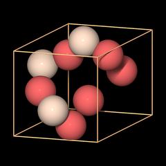
We can also recognize a key element of quartz crystal structure in it: in the lower left half there is a chain made of oxygen and silicon atoms that forms a hook. It is a part of a threefold helix, which in this case is left-handed.
Other than that, the arrangement of the atoms looks very strange and enigmatic. In particular, what is missing from it are SiO4 tetrahedra that are the essential building blocks of quartz and silicates. By placing the unit cell at that position, the tetrahedra have been ripped apart.
This model of the unit cell emphasizes the correct representation of the chemical formula.
|
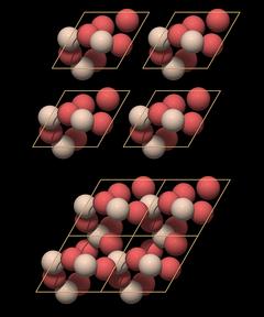
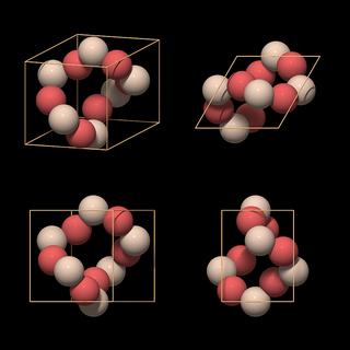
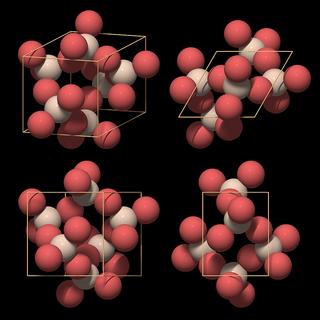
On top there are 4 isolated unit cells that are simply pushed together at the bottom. This assemblage already shows all structural elements of quartz:
- A large central channel
- Two threefold helices in each unit cell
- A sixfold double helix surrounding the large central channel
A single unit cell does enclose all essential structural elements of the quartz crystal lattice.
Now you will perhaps say, "So what? You have just extracted that unit cell from the structure, of course it works!" The point is that one just needs to know the position of the atoms in unit cell coordinates and the unit cell dimensions to construct the entire crystal structure with all its features. Which, of course, is eminently practical if you want to communicate and compare data.
|
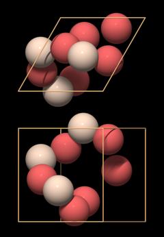
The vertical planes of the unit cell correspond to the hexagonal prism faces, the m-faces. The upper and lower face of the unit cell lie parallel to the c-plane, however, the corresponding c-face is extremely rare and apparently only found on crystals that are corroded.
|
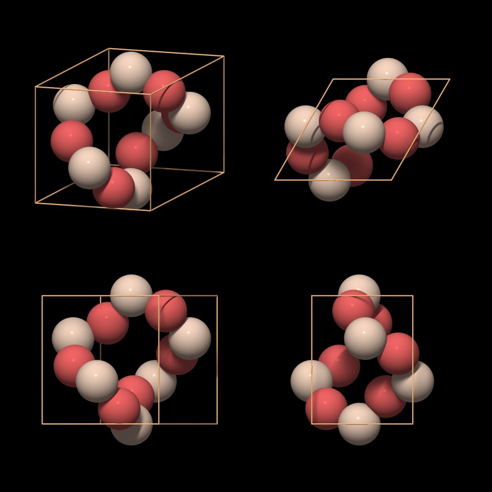
The atoms form a twisted ring in which each silicon atom occupies one of the faces of the rhomb. Such a unit cell type is called face-centered, because the lattice elements are placed within the faces of the unit cell[8]. In the top view we can see what is causing the twist in the ring: the unit cell encloses two neighboring threefold helices. The twisted rings have already been mentioned and can be recognized in Fig.5.09.
|
This model is preferred because it shows the most important structural element of quartz: the SiO4 tetrahedron. When we compare it with the "ring-type" unit cell in Fig.10.10, we see that each silicon atom has been replaced by a complete SiO4 tetrahedron.
|
Also note the lack of mirror symmetry, which is in agreement with the overall symmetry of the crystal structure. The top view looks mirror symmetric at a first glimpse, but if you take into account the three-dimensional structure you can see it is not.
|
|
Done.
Time for an Aspirin ;-)
Further Information, Literature, Links
The data of quartz unit cell coordinates for rendering these images have been downloaded from www.molecules.org.
The page The Crystal Structure of Quartz (SiO2) is a good introduction into quartz crystal structure using different views (tetrahedra, ball-and-stick, etc.). Also gives a nice demonstration of the unit cell concept applied to quartz.
An animated gif showing the transition from low to high quartz can be found on Using XtalDraw to Make Animated GIF's: The High-Temperature Phase Transition of Quartz
Crystallographic data can be retrieved from the American Mineralogist Crystal Structure Database
An interactive Java applet lets you select, multiply and visualize unit cell data of various minerals on Crystal Structures
Footnotes
1 The m-plane is a crystallographic plane parallel to one of the m-faces that form the hexagonal prism of the crystal.2 It is sufficient to take three motifs to form the inner ring of SiO4 tetrahedra around central channel.
3 I will not explain the meaning of the symbols as that is beyond the scope of this topic and I must assume a basic understanding of DNA structure. Check out the link to the Wikipedia article on DNA.
4 You will note that there are actually six directions, but they lie on only three axes, and the two directions on each axis are equivalent.
5 The fact that there are three axes is a special property of hexagonal patterns, it can only be found in structures in which the axes meet at an angle of 60°.
6 Hexagons can cover a plane completely to form a honeycomb pattern, but their edges will not join to form the straight axes of a coordinate system.
7 This is just a matter of convenience for me, as the basic data set that has been used to render all figures on this page uses the coordinates of the left unit cell model.
8 As I have already mentioned above, the fact that the unit cell is face-centered is the result of an arbitrary decision on its vertical position.
 Printer Friendly Version
Copyright © 2005-2022, A.C. A k h a v a n
Impressum - Source: http://www.quartzpage.de/gen_struct.html